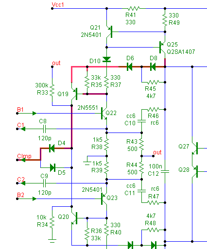
The main components of the clamp (only one half is discussed here) are: D4, Q19, D6 and D8. When active, a current
is sent back to the inverting input of the front end (node FB) In order to prevent instabilities, the clamp goes through
two phases, first soft limiting, next hard limiting. If the pre-driver (Q25) is almost saturated, additional NFB is applied
via R45, D6 and Q19 (which finally limits the output voltage of course) When Q25 is totally saturated, the feedback is
increased as D8 is also conducting now.
The crux of this two phase approach is that when the gain of the output stage is decreasing (because it gets
saturated), at the same time, the NFB factor of the clamp is gradually increased. In doing so, the phase margin of the
combined feedback loop is kept at a safe level.
In ultra low distortion amplifiers, leakage currents and the nonlinear Cob of Q19 will affect the performance. Therefore,
a threshold is incorporated by means of R33, R34, R35, and D4, which prevent them to enter the signal path.
Notice that, opposed to other schemes, this clamp is still active (giving more feedback proportional to the input
voltage), even when Q25 is completely saturated.
One may wonder why doing it the hard way? The answer is that this approach precisely detects where (the driver) and
why (saturation) it goes wrong at the onset of clipping. One more reason is that it works completely independent of the
VAS supply voltage or component tolerances. Opposed to a more conventional approach, the VAS hasn't to 'guess'
when the output stage runs out of steam.
Q&A's (extracted from personal email)
Q: Q21/R41/R42/Q24, is it a current mirror, or a stage with gain?
A: Yes, it is a current mirror, but the 'gain' is just 1x (because R41=R49). BTW, this arrangement might look peculiar
as the quiescent current has a negative tempco, but the preceding stage (Q22/Q23) has a positive tempco, so the
net tempco is zero (because R38 || R43 = R41).
Q: If I understand correctly, the sensor is Q19/Q20, and the output is sent to inverting (FB) input. Will this cause
oscillation?
A: Indeed, both units send a signal back to the inverting input (node FB), but not at the same time. If the amp
operates under normal conditions, the inverting input only receives feedback from the output and the clamp does
nothing. During clamping however, the AC gain of the output stage is largely reduced and now the clamp gets active
and takes over the feedback to about the same extent (keeping the total amount of feedback roughly at the same
level). So with respect to feedback, it's not and-and, rather exclusive-or, thus no fear of oscillations (at least, that's
intention of this circuit)
Q: Usually, anti-clipping is working locally, However, you send the anti-clipping signal to the inverting (FB) input. If the
output (i.e. one of the collectors of Q19 or Q20) is sending a signal to the emitters of Q22/Q23 (instead of to the
inverting input), is this a violating the core of your idea?
A: That's a good question and I have tried that too (read: simulated), but such arrangement only prevents saturating
of the output stage, not the VAS etc. Therefore I send the anti-clipping signal right to the beginning of the whole signal
path, as now all stages are protected from saturation or over-drive.
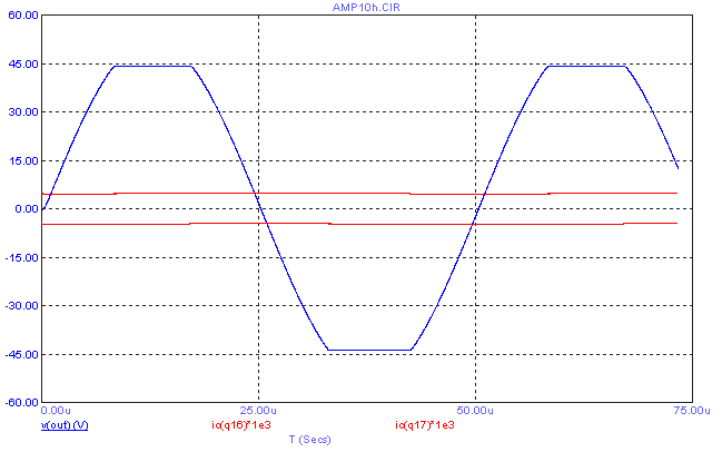
Overdrive response at 20kHz. Notice that the VAS currents (red curves) are unaffected.